VLSM
Variable Length Subnet Masking
Efficient IP address allocation — from first principles to real-world deployment
🌐 What is VLSM?
Variable Length Subnet Masking (VLSM) is a classless IP subnetting technique that allows a network administrator to divide an IP address space into subnets of different sizes — each with its own unique subnet mask — rather than forcing every subnet to be the same length. The core idea is simple yet powerful: allocate only as many IP addresses as a given network segment actually needs, and nothing more.
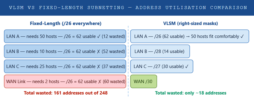
Before VLSM, classical subnetting (classful networking) required every subnet within a network to use the same prefix length. If you needed a /24 somewhere, every segment got a /24 — even a point-to-point WAN link that only required two addresses. This led to catastrophic address waste in environments with diverse host requirements.
VLSM is considered a foundational IP addressing skill. It underpins every efficient network design, from small branch offices to service-provider backbones, and is inseparable from CIDR (Classless Inter-Domain Routing), which applies the same variable-mask concept at an inter-domain scale.
Put simply: VLSM lets you right-size every subnet to its actual requirement, dramatically improving IP address utilisation and simplifying route summarisation.
🧩 Components
To implement VLSM correctly, you need to understand the building blocks that govern how IP address space is subdivided. Each component plays a distinct role in determining what a subnet can do and how it relates to the broader addressing hierarchy.
IP Address
A 32-bit (IPv4) or 128-bit (IPv6) logical identifier assigned to a network interface. In VLSM, the IP address combined with its subnet mask defines the network and host portions of the address space.
Subnet Mask
A 32-bit value written in dotted-decimal or CIDR prefix notation (e.g., 255.255.255.0 = /24) that separates the network bits from the host bits. In VLSM, each subnet has its own unique mask.
Network Address
The first address in any subnet — all host bits set to zero. This address is not assignable to any device; it identifies the subnet itself in routing tables and calculations.
Broadcast Address
The last address in a subnet — all host bits set to one. Packets sent to this address are delivered to every host on the subnet. Like the network address, it is not assignable.
Usable Host Range
All addresses between the network and broadcast addresses. The formula is 2n–2, where n equals the number of host bits. This is the pool of addresses you assign to devices.
CIDR Prefix Length
The /n notation indicating how many bits are used for the network portion. Ranges from /0 (no masking) to /32 (a single host). VLSM leverages this flexibility to create subnets of any size.
Routing Protocol
A classless routing protocol (OSPF, EIGRP, IS-IS, BGP, RIPv2) is mandatory for VLSM. These protocols advertise the subnet mask with each route, allowing routers to differentiate between differently-sized subnets.
Address Block
The parent IP address range from which all VLSM subnets are carved. Efficient VLSM design starts by allocating the largest subnets first, then progressively smaller ones from the remaining space.
⚙️ How It Works
VLSM works by recursively subdividing a parent address block into smaller and smaller subnets, each sized precisely to meet the host requirements of a given network segment. The process is methodical: list all your subnets by host requirement from largest to smallest, allocate the first (and largest) block, then carve the next subnet from the remaining space.
The VLSM Calculation Process
List every subnet you need — LANs, WAN links, DMZ segments, loopbacks. Record the number of required hosts for each. Include growth headroom (typically 20–30%).
Always allocate the largest subnet first. This prevents fragmentation and ensures the smallest subnets (e.g., /30 WAN links) can be neatly carved from the remaining space.
Find the smallest power of 2 that is ≥ (required hosts + 2). The prefix length is 32 minus the number of host bits. For example: 50 hosts → need 64 addresses → 6 host bits → /26.
Assign the next available, properly aligned address range. The subnet must start on a boundary that is a multiple of its block size. Mark the network address, broadcast, and usable range.
After each allocation, identify what address space remains. The next subnet is carved from this remainder, moving forward through the parent block systematically.
Record every subnet: network address, mask, usable range, broadcast, and assigned purpose. Verify no subnets overlap and the entire allocation fits within the parent block.
Example: 192.168.10.0/24
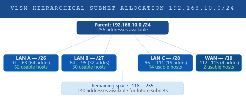
Consider a scenario where you need to subnet 192.168.10.0/24 for the following requirements: 60 hosts on LAN A, 28 hosts on LAN B, 12 hosts on LAN C, and a point-to-point WAN link needing just 2 addresses.
Parent block: 192.168.10.0 /24 (256 addresses)
═══════════════════════════════════════════════════════════════Step 1 — LAN A: 60 hosts → need 62 usable → /26 (64 addresses)
Network: 192.168.10.0 Mask: /26 (255.255.255.192)
Usable: 192.168.10.1 – 192.168.10.62
Broadcast: 192.168.10.63
Step 2 — LAN B: 28 hosts → need 30 usable → /27 (32 addresses)
Network: 192.168.10.64 Mask: /27 (255.255.255.224)
Usable: 192.168.10.65 – 192.168.10.94
Broadcast: 192.168.10.95
Step 3 — LAN C: 12 hosts → need 14 usable → /28 (16 addresses)
Network: 192.168.10.96 Mask: /28 (255.255.255.240)
Usable: 192.168.10.97 – 192.168.10.110
Broadcast: 192.168.10.111
Step 4 — WAN: 2 hosts → need 2 usable → /30 (4 addresses)
Network: 192.168.10.112 Mask: /30 (255.255.255.252)
Usable: 192.168.10.113 – 192.168.10.114
Broadcast: 192.168.10.115
═══════════════════════════════════════════════════════════════
Addresses used: 116 (45.3% of /24)
Addresses free: 140 (available for future subnets)
Binary Mask Anatomy
Understanding how the subnet mask operates at the binary level is essential for confident VLSM work. The mask is a contiguous sequence of 1s (network portion) followed by contiguous 0s (host portion). ANDing the IP address with the mask always yields the network address.
IP Address:   192.168.10. 97  =  11000000.10101000.00001010.01100001

Subnet Mask:  255.255.255.240  =  11111111.11111111.11111111.11110000

                                              ──────────── ────────

                                              Network bits  Host bits

AND result:   192.168.10. 96  =  Network address (all host bits → 0)

Broadcast:    192.168.10.111  =  Broadcast addr  (all host bits → 1)
<
📊 Usage & Functions
VLSM is not merely an academic exercise — it is a practical tool used daily in enterprise network design, service provider infrastructure, cloud networking, and cybersecurity architectures. Its functions span from basic IP conservation to enabling sophisticated routing optimisations.
| Use Case | Typical Prefix | Function | Example Scenario |
|---|---|---|---|
| Large LAN Segment | /22 – /24 | Host-dense segments in data centres or campus floors | Server farm requiring 500+ hosts |
| Standard LAN | /25 – /27 | Departmental networks with moderate host counts | HR or Finance department with 30–50 workstations |
| Small VLAN / DMZ | /28 – /29 | Isolated segments for servers or IoT clusters | Web server DMZ with 6 public-facing hosts |
| Point-to-Point WAN | /30 | Serial or Ethernet WAN links needing exactly 2 routable IPs | MPLS PE-to-CE link or leased-line interconnect |
| Point-to-Point (modern) | /31 | RFC 3021 — eliminates the network/broadcast overhead on P2P links | Service provider core links; Cisco IOS supports /31 on routed ports |
| Loopback Interfaces | /32 | Unique host route for router identity; used in OSPF router-ID, BGP peering | OSPF router-ID assignment; BGP loopback peering |
| Route Summarisation | /16 – /23 | Aggregate multiple contiguous VLSM subnets into a single summary route | Summarising 192.168.0.0/24 – 192.168.3.0/24 as 192.168.0.0/22 |
VLSM in Cisco IOS Configuration
From a configuration standpoint, VLSM is transparent — you simply assign the appropriate subnet mask to each interface. The routing protocol handles the rest, as long as it is classless. Below is an example of configuring interfaces with VLSM-derived addresses on a Cisco router:
! Configure LAN A interface (/26)
Router(config)# interface GigabitEthernet0/0
Router(config-if)# ip address 192.168.10.1 255.255.255.192
Router(config-if)# no shutdown! Configure LAN B interface (/27)
Router(config)# interface GigabitEthernet0/1
Router(config-if)# ip address 192.168.10.65 255.255.255.224
Router(config-if)# no shutdown
! Configure WAN serial link (/30)
Router(config)# interface Serial0/0/0
Router(config-if)# ip address 192.168.10.113 255.255.255.252
Router(config-if)# no shutdown
! Configure Loopback for OSPF Router-ID (/32)
Router(config)# interface Loopback0
Router(config-if)# ip address 10.0.0.1 255.255.255.255
! Enable OSPF (classless — supports VLSM natively)
Router(config)# router ospf 1
Router(config-router)# network 192.168.10.0 0.0.0.255 area 0
show ip route to confirm that the routing table correctly shows each subnet with its unique prefix length (e.g., C 192.168.10.0/26, C 192.168.10.64/27). If you see classful summaries, check that no ip classless is not applied and your routing protocol is classless.VLSM and Route Summarisation
One of the most powerful functions of VLSM is its compatibility with route summarisation (also called route aggregation or supernetting). When VLSM subnets are allocated contiguously from the same parent block, they can often be summarised into a single route advertisement — reducing routing table size, CPU overhead, and convergence time across the wider network.
Individual routes in the routing table:
192.168.10.0/26 (LAN A)
192.168.10.64/27 (LAN B)
192.168.10.96/28 (LAN C)
192.168.10.112/30 (WAN link)Summary route advertised to upstream routers:
192.168.10.0/24 → 4 routes reduced to 1 advertisement
Cisco IOS — configure summary on OSPF:
Router(config-router)# area 0 range 192.168.10.0 255.255.255.0
✅ Best Practices
After years of designing and troubleshooting enterprise networks, certain patterns consistently produce clean, scalable VLSM designs — while common mistakes tend to repeat. The following practices reflect real-world operational experience.
- Always plan on paper before configuring. Build a complete IP address allocation table before touching a single router. Documenting every subnet — including its purpose, host count, mask, network address, and broadcast — prevents overlaps and makes troubleshooting dramatically easier months later.
- Allocate from largest to smallest. This is the cardinal rule of VLSM. Starting with the largest subnet prevents fragmentation of your address space and ensures smaller subnets can be cleanly carved from remaining blocks without alignment issues.
- Factor in growth — add 20–30% headroom. Never allocate the exact number of current hosts. Networks grow. A /28 that perfectly fits 14 hosts today may not accommodate the 20 hosts needed in eighteen months. Account for planned growth in your mask selection.
- Use /30 or /31 for all point-to-point WAN links. Never waste a /24 or /27 on a link that only needs two addresses. /30 is the classic choice; /31 (RFC 3021) is increasingly preferred on modern Cisco and multi-vendor gear for its additional two-address savings per link.
- Assign loopbacks as /32 host routes. Router loopback interfaces used for OSPF Router-IDs, BGP peering, or network management should always use /32 masks. They are host-specific and should never be broadcast as a wider subnet.
- Design for summarisability. Whenever possible, allocate contiguous address blocks to each site, region, or functional group. Contiguous allocations can be summarised into a single route advertisement, keeping routing tables compact and convergence fast.
- Use a standardised addressing scheme. Adopt consistent conventions: for example, always assign the first usable address in a subnet to the default gateway, and the last to a management interface. This reduces cognitive load for all engineers on the team and speeds up fault isolation.
- Document everything in an IPAM solution. Manual spreadsheets work for small networks, but even a modest enterprise should use an IP Address Management (IPAM) tool — such as Infoblox, SolarWinds IP Address Manager, or open-source phpIPAM — to track allocations, prevent conflicts, and maintain audit trails.
- Validate with “show ip route” and a subnet calculator. Always verify your configured subnets appear in the routing table with the correct prefix length. Use a subnet calculator (or write the binary yourself for exam practice) to confirm there are no boundary violations.
- Do not mix classful and classless protocols. If you are running VLSM, every routing protocol in the topology must be classless. A single RIPv1 process in the domain can cause routing black holes by summarising your carefully designed VLSM subnets into incorrect classful boundaries.
⚖️ Pros & Cons
Like any technology, VLSM carries trade-offs. Understanding both the advantages and the limitations ensures you deploy it appropriately and manage the operational complexity it introduces.
✔ Advantages
- Dramatically reduces IP address waste by allocating only what each segment needs
- Enables efficient use of scarce public IPv4 address space in ISP and enterprise environments
- Supports route summarisation, reducing routing table size and improving convergence speed
- Scales from small branch offices to large enterprise and service-provider backbones
- Compatible with all modern classless routing protocols (OSPF, EIGRP, IS-IS, BGP)
- Enables clean security segmentation with appropriately sized subnets per zone
- Allows /30 and /31 WAN links, reducing addressing overhead on P2P connections
- Supported natively by all modern operating systems, routers, and switches
- Facilitates hierarchical network design, making large networks easier to manage
✘ Disadvantages
- More complex to plan and calculate than fixed-length subnetting — errors are common without documentation
- Requires classless routing protocols throughout the entire network — no RIPv1
- Troubleshooting routing issues can be more challenging with variable masks in the table
- Poor initial planning leads to address fragmentation, making later readdressing necessary
- Steep learning curve for junior network engineers unfamiliar with binary mask arithmetic
- Without IPAM tooling, manual tracking of VLSM allocations becomes error-prone at scale
- Subnet boundary misalignment errors are difficult to diagnose without binary analysis
- Overlapping subnet allocations can cause silent routing failures that are hard to detect
🎯 Conclusion
Variable Length Subnet Masking is one of the most consequential techniques in IP network design. By abandoning the one-size-fits-all rigidity of classful addressing, VLSM empowers engineers to build networks that are both address-efficient and architecturally sound — qualities that matter whether you are managing a single office or a multi-site enterprise spanning continents.
Learning VLSM is non-negotiable. It underpins every real-world subnetting task you will encounter. The methodology is consistent: inventory your needs, sort largest to smallest, calculate prefix lengths, allocate contiguously, and document religiously.
As IPv6 adoption continues to grow, the address-scarcity problem that made VLSM essential for IPv4 diminishes — but the design principles it embodies (right-sizing, segmentation, summarisation) remain just as relevant in an IPv6 world. Understanding VLSM deeply makes you a better network architect regardless of the address family you are working with.
If there is a single piece of practical advice to take away: always plan your VLSM scheme on paper before configuring anything. A well-documented addressing plan is the difference between a network that scales gracefully and one that requires painful readdressing every eighteen months.
📖 Glossary
Mask
Length
Address
Address
Routing
Routing
Summary
Mask
RFC 1812