Network Devices
Hardware & software components
Components that build, segment and secure networks
📝 Table of Contents
🌐 What Are Network Devices?
Network devices are the physical and logical components that enable data communication between endpoints across a network infrastructure. Whether you are building a small office LAN or architecting a multi-site enterprise WAN, every path a packet travels passes through one or more network devices that inspect, forward, filter, or amplify the signal. Understanding these devices at a functional and configuration level is foundational to any networking career.
At their core, network devices operate at specific layers of the OSI (Open Systems Interconnection) model. A hub operates at Layer 1 (Physical), rebroadcasting electrical signals without any intelligence. A switch operates primarily at Layer 2 (Data Link), making forwarding decisions based on MAC addresses. A router operates at Layer 3 (Network), using IP routing tables to determine the best path for a packet. More sophisticated devices, such as multilayer switches, firewalls, and load balancers, operate across multiple OSI layers simultaneously, applying complex policies based on IP addresses, port numbers, application signatures, and even user identity.
The distinction matters because each layer of the OSI model introduces a different level of granularity and intelligence. A Layer 2 switch can segment collision domains and build MAC address tables, but it cannot separate broadcast domains — that requires a Layer 3 device. Understanding this layered context allows engineers to select the right device for each requirement, minimise unnecessary broadcast traffic, enforce security policies at the correct point in the data path, and troubleshoot problems with precision rather than guesswork.
Network devices can be broadly categorised into three functional roles: connectivity devices (hubs, switches, access points) that link hosts together at Layer 1 or 2; routing and inter-network devices (routers, multilayer switches) that connect different networks or VLANs at Layer 3; and security and control devices (firewalls, IDS/IPS, proxies) that enforce policies and protect the network perimeter and interior. Modern network infrastructure often merges these roles — a next-generation firewall may perform routing, VPN termination, intrusion prevention, and deep packet inspection all within a single chassis.
The ability to identify which device performs which function, articulate how each device processes frames or packets, and configure those devices using Cisco IOS is essential. For working engineers, a deep understanding of network devices informs every architectural decision — from choosing between a Layer 3 switch and a router for inter-VLAN routing, to deciding where to place an IPS sensor for maximum visibility.
🧩Key Components
Modern networks are built from a diverse set of network devices, each engineered for a specific purpose within the OSI model. The following cards describe the primary network device types you will encounter in enterprise and SMB environments, along with their operating layer, primary function, and relevance to Cisco IOS deployments.
Switch
A Layer 2 device that builds a MAC address table and forwards frames only to the correct destination port. Eliminates collisions per-port and supports VLANs to segment broadcast domains.
Router
A Layer 3 device that forwards packets between networks using IP routing tables. Separates broadcast domains and supports static and dynamic routing protocols such as OSPF, EIGRP, and BGP.
Firewall
Operates at Layers 3–7. Enforces access control policies based on IP, port, protocol, and application data. Next-generation firewalls (NGFW) add IPS, URL filtering, and application awareness.
Wireless Access Point
Bridges 802.11 wireless clients onto a wired Ethernet network at Layer 2. May operate in autonomous or controller-managed (lightweight) mode. Supports multiple SSIDs mapped to VLANs.
Multilayer Switch
Combines Layer 2 switching and Layer 3 routing in a single device. Ideal for high-speed inter-VLAN routing within a campus network. Uses hardware ASICs for wire-speed forwarding.
Network Bridge
A Layer 2 device that connects two network segments and filters traffic based on MAC addresses. Predecessor to the modern switch; still relevant conceptually for understanding spanning tree protocol.
Load Balancer
Distributes incoming traffic across multiple servers or links to optimise resource utilisation and ensure high availability. Operates at Layer 4 (TCP/UDP) or Layer 7 (HTTP/HTTPS application content).
Modem
Modulates and demodulates signals to enable data transmission over telephone lines, cable, or fibre. Acts as the demarcation point between the service provider network and the customer premises equipment.
IDS / IPS
Intrusion Detection/Prevention Systems inspect packets for known attack signatures and anomalous behaviour. An IDS alerts passively; an IPS sits inline and can drop malicious traffic in real time.
⚙️ How It Works
Understanding how network devices process traffic requires tracing a packet’s journey from source to destination. Each device type applies a distinct set of logic at its respective OSI layer. The following step-by-step breakdown follows a frame generated by a PC in VLAN 10 as it reaches a web server in a different subnet — a scenario that exercises switches, routers, and firewalls in sequence.
The source PC encapsulates its IP packet within an Ethernet frame. It populates the source MAC address with its own NIC address and the destination MAC address with the gateway’s MAC (resolved via ARP). The frame is converted to a bitstream and placed onto the physical medium.
The switch receives the frame on an access port assigned to VLAN 10. It reads the source MAC address and records it in the CAM (Content Addressable Memory) table against the ingress port. It then looks up the destination MAC address. If a matching entry exists, the frame is forwarded only to that port. If not, the switch floods the frame out all ports in VLAN 10 except the ingress port.
If the destination is in a different VLAN, the frame travels up a trunk link to a distribution or core switch. The switch inserts an 802.1Q VLAN tag (4 bytes) into the Ethernet header, identifying the originating VLAN. Trunk ports carry multiple VLANs simultaneously using this tagging mechanism.
The Layer 3 device receives the frame on its SVI (Switched Virtual Interface) or routed sub-interface. It strips the Ethernet header, examines the destination IP address, and performs a longest-prefix match against the routing table. The packet is then re-encapsulated in a new Ethernet frame with the next-hop MAC address and forwarded toward the destination network.
Before the packet reaches the server segment, the firewall performs stateful inspection. It checks whether this flow matches an existing state table entry. If not, it evaluates the packet against the access control policy. A stateless firewall checks only the packet header; a next-generation firewall may also perform application identification, URL categorisation, and malware scanning.
The server-side access switch receives the forwarded frame, looks up the server’s MAC address in its CAM table, and delivers the frame to the correct port. The server’s NIC accepts the frame, strips the Ethernet header, and passes the IP packet up the protocol stack to the application layer.
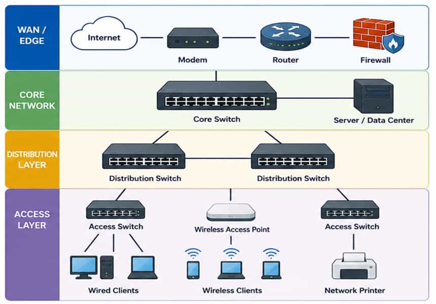
Network Topology: Device Placement Visualised
The diagram below illustrates a typical three-tier enterprise network topology, showing the logical placement of each network device type from the Internet edge down to end hosts.
Switch CAM Table Operation
When a switch boots, its CAM table is empty. As frames arrive, the switch performs three operations: learning (records source MAC and ingress port), forwarding (sends the frame to the known destination port), and flooding (sends to all ports in the VLAN if the destination MAC is unknown). CAM table entries age out after a configurable period (default 300 seconds on Cisco IOS), freeing space for active hosts.
Router Forwarding: Longest Prefix Match
When a router receives a packet, it performs a lookup in the routing table, comparing the destination IP against every prefix. The route with the most specific (longest) prefix mask wins. For example, if both 10.0.0.0/8 and 10.10.10.0/24 exist in the routing table, a packet destined for 10.10.10.50 matches the /24 entry. If no match exists, the packet is forwarded to the default route (0.0.0.0/0) or dropped with an ICMP Unreachable message sent to the source.
Connected routes: AD 0,
Static: AD 1,
EIGRP internal: AD 90,
OSPF: AD 110,
RIP: AD 120.
Memorise these values — they appear frequently in exam scenarios.
Cisco IOS: Switch Configuration Example
The following example configures an access port for VLAN 10 and a trunk port on a Cisco Catalyst switch, along with verification commands to confirm the configuration is applied correctly.
! Create VLANs in the VLAN database
SW1(config)# vlan 10
SW1(config-vlan)# name USERS
SW1(config-vlan)# exit
SW1(config)# vlan 20
SW1(config-vlan)# name SERVERS
SW1(config-vlan)# exit! Configure access port (Gi0/1) for VLAN 10
SW1(config)# interface GigabitEthernet0/1
SW1(config-if)# switchport mode access
SW1(config-if)# switchport access vlan 10
SW1(config-if)# spanning-tree portfast
SW1(config-if)# no shutdown
! Configure trunk port (Gi0/24) to distribution switch
SW1(config)# interface GigabitEthernet0/24
SW1(config-if)# switchport trunk encapsulation dot1q
SW1(config-if)# switchport mode trunk
SW1(config-if)# switchport trunk allowed vlan 10,20
SW1(config-if)# no shutdown
! Verify: show MAC address table and VLAN assignments
SW1# show mac address-table
SW1# show vlan brief
SW1# show interfaces trunk
Cisco IOS: Router Inter-VLAN Routing (Router-on-a-Stick)
The following example configures a Cisco router to perform inter-VLAN routing using sub-interfaces on a single physical trunk link — the “router-on-a-stick” topology commonly tested in CCNA examinations.
! Enable the physical interface
R1(config)# interface GigabitEthernet0/0
R1(config-if)# no shutdown! Sub-interface for VLAN 10
R1(config)# interface GigabitEthernet0/0.10
R1(config-subif)# encapsulation dot1Q 10
R1(config-subif)# ip address 192.168.10.1 255.255.255.0
! Sub-interface for VLAN 20
R1(config)# interface GigabitEthernet0/0.20
R1(config-subif)# encapsulation dot1Q 20
R1(config-subif)# ip address 192.168.20.1 255.255.255.0
! Verify routing table and interface status
R1# show ip route
R1# show ip interface brief
R1# ping 192.168.20.10 source 192.168.10.1
📊Usage and Functions
Each category of network device fulfils a distinct role within network infrastructure. The table below maps common deployment use cases to their device function and how that function manifests within Cisco IOS — bridging the gap between theory and hands-on configuration.
| Use Case | Function | Cisco IOS |
|---|---|---|
| LAN Segmentation | VLAN creation on a Layer 2 switch separates broadcast domains, reducing unnecessary traffic and improving security between departments. | vlan <id>, switchport access vlan, show vlan brief |
| Inter-VLAN Routing | A multilayer switch or router with sub-interfaces routes IP packets between VLANs at Layer 3, enabling cross-segment communication. | ip routing, SVIs via interface vlan <id>, or sub-interfaces with encapsulation dot1Q |
| WAN Connectivity | A router connects the enterprise LAN to the service provider WAN, running dynamic routing protocols such as OSPF or BGP toward the upstream provider. | router ospf <pid>, network <prefix>, show ip ospf neighbor |
| Perimeter Security | A firewall enforces stateful inspection and ACL-based policies at the network edge, controlling inbound and outbound flows between trusted and untrusted zones. | IOS ACLs: ip access-list extended, permit/deny, applied with ip access-group on the interface |
| Wireless Access | An 802.11 access point bridges wireless clients to the wired network. In controller-managed deployments, the AP uses CAPWAP tunnels to a Wireless LAN Controller (WLC). | Cisco WLC managed via GUI or show ap summary, SSID-to-VLAN mapping configured on the WLC |
| Redundancy & STP | Spanning Tree Protocol prevents Layer 2 loops in redundant switch topologies by placing ports in blocking, listening, learning, or forwarding states. | spanning-tree mode rapid-pvst, spanning-tree vlan <id> root primary, show spanning-tree |
| DHCP Service | A router or Layer 3 switch can act as a DHCP server, dynamically assigning IP addresses, subnet masks, default gateways, and DNS servers to hosts on each VLAN. | ip dhcp pool, network, default-router, dns-server, ip dhcp excluded-address |
| Traffic Monitoring | SPAN (Switched Port Analyser) mirrors traffic from a source port or VLAN to a destination port connected to a network analyser or IDS sensor. | monitor session 1 source interface Gi0/1, monitor session 1 destination interface Gi0/24 |
| QoS Enforcement | Network devices classify and mark traffic using DSCP or CoS values, then apply queuing policies to prioritise voice and video over bulk data transfers. | class-map, policy-map, service-policy, mls qos on Catalyst switches |
| NAT / PAT | Network Address Translation on a border router translates private internal addresses to a public IP (overloaded NAT / PAT), enabling multiple hosts to share a single public address. | ip nat inside source list <acl> interface <if> overload, show ip nat translations |
✅Best Practices
Deploying and maintaining network devices effectively requires adherence to a set of proven principles. These practices reduce attack surface, improve network stability, simplify troubleshooting, and align with Cisco hardening guidelines and industry frameworks such as CIS Benchmarks.
- Segment the network using VLANs: Never place all hosts on a single flat Layer 2 network. Use VLANs to logically separate users, servers, VoIP, management, and IoT devices. This limits the blast radius of broadcast storms and significantly reduces lateral movement in the event of a host compromise.
- Harden management access on all devices: Disable Telnet and use SSH version 2 for all CLI access. Restrict management access to a dedicated out-of-band management VLAN. Apply access class ACLs to VTY lines to permit only authorised management subnets.
- Apply the principle of least privilege to ACLs: Write access control lists that explicitly permit required traffic and deny everything else with an implicit or explicit deny-all at the end. Regularly review and audit ACLs — unused permit rules are a common source of unintended exposure.
- Enable BPDU Guard and PortFast on access ports: PortFast bypasses the Spanning Tree listening and learning states on ports connected to end hosts, reducing link-up delay. BPDU Guard immediately error-disables any access port that receives a BPDU, preventing rogue switches from being connected to the network.
- Use Rapid PVST+ or MSTP for Spanning Tree: Legacy 802.1D STP has a convergence time of up to 50 seconds. Rapid PVST+ (IEEE 802.1w) converges in under a second. In large networks with many VLANs, consider Multiple Spanning Tree Protocol (MSTP) to group VLANs into a smaller number of spanning tree instances, reducing CPU overhead.
- Implement DHCP Snooping and Dynamic ARP Inspection: DHCP Snooping builds a binding table of authorised MAC-to-IP mappings and blocks rogue DHCP servers on untrusted ports. Dynamic ARP Inspection uses the snooping binding table to validate ARP replies, preventing ARP spoofing and man-in-the-middle attacks.
- Standardise device naming and documentation: Use a consistent, descriptive naming convention for all network devices (e.g., SITE-ROLE-NUMBER: SYD-ACCESS-SW-01). Maintain up-to-date network diagrams showing physical and logical topologies, IP addressing, VLAN assignments, and cable schedules. Documentation is the foundation of fast troubleshooting.
- Use NTP for synchronised clock sources: Configure all network devices to synchronise time from a reliable NTP hierarchy. Consistent timestamps across all devices are essential for correlating syslog events, debugging security incidents, and meeting audit and compliance requirements.
- Deploy centralised logging and monitoring: Configure all network devices to forward syslog messages to a centralised SIEM or log management platform. Set logging levels appropriately — informational for normal operations, debugging only for active troubleshooting. Monitor interface error counters, CPU utilisation, and memory thresholds via SNMP.
- Test and document change management procedures: Never apply configuration changes to production devices without following a formal change management process. This includes pre-change testing in a lab or simulation environment, rollback plans, approved change windows, and post-change verification using show commands and connectivity tests.
copy running-config startup-config (or wr for short) to persist the changes. A device that reboots unexpectedly without saving will lose all running configuration changes — a common and costly oversight in production environments.⚖️Pros and Cons
Like any technology, network devices come with inherent trade-offs. The advantages and disadvantages below reflect the realities of deploying dedicated hardware network devices versus software-defined or virtualised alternatives, as well as the practical challenges of managing distributed physical infrastructure.
✔ Advantages
- Dedicated hardware ASICs provide wire-speed forwarding performance that general-purpose CPUs cannot match, especially for high-throughput environments.
- Mature, vendor-supported operating systems (Cisco IOS, IOS-XE, NX-OS) with extensive documentation, training resources, and a global community of engineers.
- Clear OSI-layer segmentation allows precise troubleshooting — isolating faults to Layer 1 (physical), Layer 2 (switching), or Layer 3 (routing) problems quickly.
- Physical network devices provide predictable, deterministic latency, critical for real-time applications such as VoIP, video conferencing, and industrial control systems.
- VLAN-based segmentation and hardware-enforced ACLs provide robust security boundaries between network zones without relying on software enforcement.
- Enterprise-grade network devices offer high availability features — redundant power supplies, hot-swappable modules, and HSRP/VRRP gateway redundancy protocols.
- Standards-based protocols (802.1Q, OSPF, BGP, 802.11) ensure interoperability across vendors, reducing vendor lock-in at the protocol level.
✘ Disadvantages
- Physical hardware has significant capital expenditure requirements. Enterprise-grade switches and routers represent substantial upfront investment compared to virtualised alternatives.
- Firmware and software upgrades on network devices can require downtime or careful scheduling, creating operational risk during maintenance windows.
- Physical devices have a fixed port count and forwarding capacity. Scaling requires additional hardware procurement, rack space, and cabling — less agile than cloud-based networking.
- Managing distributed physical network devices at scale requires considerable operational effort, including consistent configuration management and change control across potentially hundreds of devices.
- Hardware end-of-life and end-of-support cycles force periodic equipment refresh cycles, adding long-term budget pressure and project risk.
- Physical cabling, power, and cooling requirements add complexity and cost, especially in multi-site deployments and data centre environments.
- Misconfigured network devices — particularly ACLs, routing protocols, and spanning tree — can cause widespread outages that are difficult to diagnose without systematic methodology.
🎯 Conclusion
Network devices are the physical and logical foundation of every modern data communication system. From the humble hub that flooded traffic indiscriminately to the next-generation firewall that identifies applications and users by name, each device in your network plays a precise role at a specific layer of the OSI model. Understanding that role — and how it maps to Cisco IOS configuration — is what separates a competent network engineer from a truly effective one.
The most important principles to carry forward are: always design with the OSI model in mind, segment your network using VLANs, secure every device at the management and data planes, and document everything. Switches, routers, firewalls, and access points do not operate in isolation — they form an interdependent system where a misconfiguration in one device can cascade failures across the entire network.
For Networking students, mastering the material in this guide provides a strong conceptual and practical foundation. The Cisco IOS CLI examples shown here — switch port configuration, trunking, router-on-a-stick inter-VLAN routing, and ACL application — are all representative of real exam tasks and real-world engineering scenarios. Practice in a lab environment such as Cisco Packet Tracer or GNS3 until they are second nature.
For engineers already in the field, the best practices section serves as a useful operational checklist. Security hardening, NTP synchronisation, centralised logging, and disciplined change management are not optional refinements — they are the difference between a network that fails gracefully and one that fails catastrophically. Invest the time to build these practices into your team’s standard operating procedures.
📖Glossary
The following terms represent core vocabulary for understanding network devices. Familiarity with these definitions is essential for practical networking work.
vlan command.Table
router ospf <process-id> to enable it.Snooping
interface vlan <id> in Cisco IOS.