STP
Spanning Tree Protocol
STP from the ground up — how it prevents broadcast storms, elects root bridges,
and keeps your switched network loop-free and resilient.
🌐What is Spanning Tree Protocol?
Spanning Tree Protocol (STP) is a Layer 2 network protocol standardised under IEEE 802.1D that prevents switching loops in Ethernet networks. Without it, a redundant topology — where multiple physical paths exist between switches — would cause frames to circulate indefinitely, consuming all available bandwidth and rendering the network unusable in seconds.
To understand why STP matters, consider what happens without it. Ethernet frames have no Time-To-Live (TTL) field equivalent at Layer 2. If a loop exists and a broadcast frame enters the network, every switch on every redundant path will forward that frame repeatedly, creating a broadcast storm. Within moments, CPU utilisation on every switch spikes, MAC address tables become unstable, and legitimate traffic is crowded out entirely. This is not a theoretical edge case — it is the predictable result of any Layer 2 loop.
STP solves the loop problem by intelligently placing certain switch ports into a blocking state, logically removing redundant paths from the active forwarding topology. The result is a loop-free, tree-shaped active network that still retains physical redundancy. If a link fails, STP reconverges and activates a previously blocked path, restoring connectivity without administrator intervention.
Within the Cisco ecosystem, STP manifests in several variants. Classic STP (802.1D) is the original, but Cisco introduced Per-VLAN Spanning Tree Plus (PVST+), which runs a separate STP instance for each VLAN, enabling per-VLAN load balancing. This was later enhanced to Rapid PVST+, combining the convergence speed of RSTP with PVST+’s per-VLAN granularity. Understanding STP at its foundation is essential for designing or troubleshooting any enterprise switched network.
At its core, STP uses a distributed algorithm — the spanning tree algorithm (STA) — in which switches exchange special messages called Bridge Protocol Data Units (BPDUs) to elect a root bridge and compute a loop-free tree. The protocol is self-healing: it continuously monitors topology changes and reconverges automatically when the network changes.
🧩Key Components
Spanning Tree Protocol relies on a precisely defined set of components that work together to elect a root, calculate path costs, and determine port roles. Mastering these building blocks is essential for real-world troubleshooting.
Root Bridge
The single switch elected as the logical centre of the spanning tree. All other switches compute their best path toward the root bridge. Election is based on lowest Bridge ID (priority + MAC address).
Bridge ID (BID)
A unique 8-byte value assigned to every switch, comprising a 2-byte bridge priority (default 32768) and a 6-byte MAC address. The BID is the primary metric used in root bridge elections.
BPDU
Bridge Protocol Data Units are the control messages switches send to share topology information. Configuration BPDUs are sent from the root every 2 seconds (Hello Timer). TCN BPDUs signal topology changes.
Path Cost
A numeric value assigned to each interface based on link speed. Lower cost is preferred. Common values: 10 Gbps = 2, 1 Gbps = 4, 100 Mbps = 19, 10 Mbps = 100. The cumulative cost to reach the root determines port roles.
Port Roles
Each port is assigned a role: Root Port (best path to root), Designated Port (forwarding port per segment), Alternate Port (backup), or Backup Port. Only Root and Designated ports forward traffic.
STP Timers
Three key timers govern STP behaviour: Hello Timer (2 sec, BPDU send interval), Forward Delay (15 sec, time spent in Listening and Learning states), and Max Age (20 sec, time before a BPDU is considered stale).
Port States
In 802.1D, ports cycle through five states: Blocking, Listening, Learning, Forwarding, and Disabled. A port moves from Blocking to Forwarding only after passing through 30 seconds of Listening and Learning.
Spanning Tree Algorithm (STA)
The distributed algorithm executed by all switches to build the loop-free tree. It combines BID comparisons, path cost calculations, and port ID tiebreakers to produce a consistent, deterministic topology.
⚙️ How It Works
The STP algorithm executes in a series of well-defined phases every time the network initialises or a topology change is detected. Understanding each phase in sequence is the key to being able to predict port states, diagnose convergence problems.
When a switch boots, it assumes it is the root bridge and begins sending Configuration BPDUs every 2 seconds out all ports. Each BPDU contains the switch’s own Bridge ID as the Root ID, a path cost of 0, and the sender’s Bridge ID. At this point, every switch believes itself to be the root.
Switches compare received BPDUs against their own. If an incoming BPDU contains a lower Root ID (lower priority value, or equal priority but lower MAC address), the receiving switch accepts the sender as the superior root, stops advertising itself as root, and begins forwarding that BPDU downstream. This continues until all switches agree on a single root bridge.
Every non-root switch identifies its Root Port (RP): the interface with the lowest cumulative path cost to the root bridge. If path costs are tied, the tiebreakers are applied in order: lowest sender Bridge ID, then lowest sender Port ID. Each non-root switch has exactly one Root Port; it is always in a Forwarding state.
On every network segment, one port is elected as the Designated Port (DP). The Designated Port is the switch interface with the lowest cost to the root on that particular segment. The root bridge’s ports are always Designated Ports. Designated Ports are placed in Forwarding state and are responsible for forwarding BPDUs and traffic onto the segment.
Any port that is neither a Root Port nor a Designated Port becomes a Non-Designated Port and is placed in the Blocking state. These ports receive BPDUs to stay aware of topology changes but do not forward data frames, effectively breaking all loops in the Layer 2 topology. Redundant paths are preserved physically but dormant logically.
When a port moves from Blocking to active, it does not begin forwarding immediately. In 802.1D it transitions through Listening (15 seconds, processes BPDUs, no frame forwarding, no MAC learning) and then Learning (15 seconds, no frame forwarding, begins populating MAC address table). After 30 seconds total, the port enters Forwarding and passes data traffic normally.
When a switch detects a link failure or state change, it sends a Topology Change Notification BPDU toward the root bridge. The root then floods a Configuration BPDU with the Topology Change (TC) bit set. Switches reduce their MAC address table aging timer from 300 seconds to the Forward Delay value (15 seconds), accelerating table refresh so traffic is forwarded on the new topology quickly.
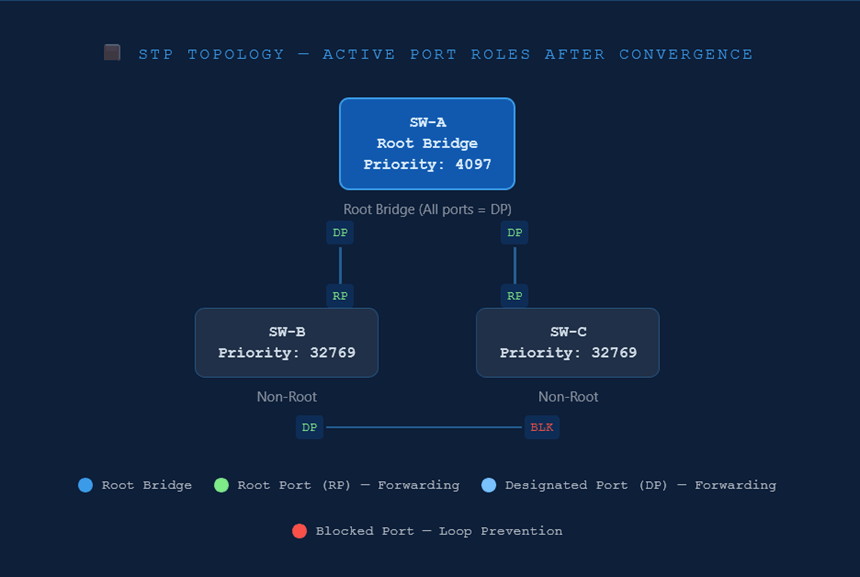
In this three-switch example, SW-A has the lowest Bridge ID and is elected root bridge. SW-B and SW-C each select their uplink to SW-A as their Root Port. On the segment connecting SW-B to SW-C, SW-B wins the Designated Port election (lower BID), so SW-C’s port on that link enters the Blocking state. The loop is broken — yet the physical link remains available for failover.
Cisco IOS CLI — Verification
SW-A# show spanning-tree vlan 1! Output (abbreviated):
VLAN0001
Spanning tree enabled protocol ieee
Root ID Priority 4097
Address 00a1.b2c3.d401
This bridge is the root
Hello Time 2 sec Max Age 20 sec Forward Delay 15 sec
Bridge ID Priority 4097 (priority 4096 sys-id-ext 1)
Address 00a1.b2c3.d401
Interface Role Sts Cost Prio.Nbr Type
Gi0/1 Desg FWD 4 128.1 P2p
Gi0/2 Desg FWD 4 128.2 P2p
! 'This bridge is the root' confirms SW-A is the root bridge.
! Gi0/1 and Gi0/2 are Designated, Forwarding — expected on root.
Cisco IOS — Full STP Hardening Configuration
The following example demonstrates a production-ready STP configuration for a distribution-layer switch acting as root bridge for VLAN 10 and VLAN 20, with PortFast, BPDU Guard, and Root Guard applied appropriately.
! Step 1 — Set STP mode to Rapid PVST+ (recommended for all modern deployments)
SW-DIST(config)# spanning-tree mode rapid-pvst! Step 2 — Configure this switch as root bridge for VLAN 10 (primary) and VLAN 20 (secondary)
SW-DIST(config)# spanning-tree vlan 10 priority 4096
SW-DIST(config)# spanning-tree vlan 20 priority 8192
! Step 3 — Enable PortFast globally on all access ports (non-trunk ports only)
SW-DIST(config)# spanning-tree portfast default
! Step 4 — Enable BPDU Guard globally (pairs with PortFast default above)
SW-DIST(config)# spanning-tree portfast bpduguard default
! Step 5 — Apply Root Guard on downlinks toward access switches (Gi1/0/10–12)
SW-DIST(config)# interface range GigabitEthernet1/0/10 - 12
SW-DIST(config-if-range)# spanning-tree guard root
! Step 6 — Apply Loop Guard on uplinks to core switches (Gi1/0/1–2)
SW-DIST(config)# interface range GigabitEthernet1/0/1 - 2
SW-DIST(config-if-range)# spanning-tree guard loop
! Step 7 — Verify the final STP state
SW-DIST# show spanning-tree summary
Switch is in rapid-pvst mode
Root bridge for: VLAN0010
Extended system ID is enabled
PortFast Default is enabled
PortFast BPDU Guard Default is enabled
Portfast BPDU Filter Default is disabled
Loopguard Default is disabled
...
📊Usage and Functions
Spanning Tree Protocol and its variants serve a variety of practical roles in modern switched networks. The table below maps common use cases to their STP function and the relevant Cisco IOS context, giving you both the conceptual understanding and the operational reference in one view.
| Use Case | STP Function | Cisco IOS Context |
|---|---|---|
| Prevent Layer 2 Broadcast Storms | Blocks redundant ports to eliminate loops; only one active path exists between any two devices at Layer 2. | Enabled by default on all Catalyst switches. Use show spanning-tree to confirm active topology. |
| Provide Link Redundancy | Maintains blocked backup paths that activate automatically upon primary link failure, ensuring high availability without loops. | Blocked ports transition to Forwarding after detecting BPDU absence for Max Age (20 sec) + 2× Forward Delay (30 sec) in 802.1D, or within 1 sec in RSTP. |
| Control Root Bridge Placement | Administrators manually set bridge priority to ensure the most capable switch (core layer) is elected root, avoiding suboptimal traffic paths. | spanning-tree vlan <id> priority <value> or the shortcut macro spanning-tree vlan <id> root primary. |
| Per-VLAN Load Balancing | PVST+ runs an independent STP instance per VLAN, allowing different root bridges per VLAN to distribute traffic across uplinks. | Set SW-A as root for VLAN 10, SW-B as root for VLAN 20 using per-VLAN priority configuration. |
| Accelerate Host Port Activation | PortFast bypasses Listening and Learning states on edge ports, enabling workstations and servers to reach the network immediately after link-up. | spanning-tree portfast on interface, or spanning-tree portfast default globally for all access ports. |
| Prevent Rogue Switch Attacks | BPDU Guard shuts down a PortFast-enabled port if a BPDU is received, blocking unauthorised switches from influencing the STP topology. | spanning-tree bpduguard enable on interface, or globally with spanning-tree portfast bpduguard default. |
| Protect Root Bridge Election | Root Guard prevents switches connected on designated ports from becoming the root bridge, enforcing the administrative topology boundary. | spanning-tree guard root on the interface facing potential rogue root switches. |
| Detect Unidirectional Link Failures | Loop Guard protects against cases where BPDUs stop arriving on a non-designated port (e.g., due to a unidirectional fibre failure) by placing the port in loop-inconsistent state rather than Forwarding. | spanning-tree guard loop on interface, or globally with spanning-tree loopguard default. |
| Rapid Failover (Sub-second) | RSTP (802.1w) and Rapid PVST+ provide near-instant convergence on point-to-point links using a proposal/agreement handshake rather than timer-based transitions. | spanning-tree mode rapid-pvst globally — the recommended setting on all modern Cisco Catalyst switches. |
✅Best Practices
A well-designed STP deployment is predictable, stable, and secure. The following best practices reflect both Cisco design guidelines and hard-won operational experience. Apply them consistently across all layer-2 domains.
-
Manually Configure the Root Bridge. Never rely on the default bridge priority to determine the root. Set the lowest priority on your core or distribution-layer switch using
spanning-tree vlan <id> priority 4096or theroot primarymacro. An unexpected root election caused by an unmanaged switch with a lower MAC address can redirect all traffic through a suboptimal path with no warning. -
Deploy Rapid PVST+ Instead of Legacy 802.1D. Configure
spanning-tree mode rapid-pvston all switches in the domain. Rapid PVST+ converges in under a second on point-to-point links compared to 30–50 seconds with classic STP. There is no reason to run 802.1D in modern networks, and the two modes interoperate with backward-compatible fallback. - Enable PortFast on All Access-Layer Edge Ports. Workstations, printers, servers, and IP phones do not participate in STP. Enabling PortFast bypasses the 30-second Listening/Learning cycle, allowing hosts to reach the network immediately after a link event. Never enable PortFast on a port connected to another switch, as it creates a loop risk.
-
Always Pair PortFast with BPDU Guard. A PortFast port that receives a BPDU is likely connected to an unauthorised or misconfigured switch. BPDU Guard immediately error-disables the port (
spanning-tree bpduguard enable), containing the threat. Enable it per interface or globally withspanning-tree portfast bpduguard default. - Apply Root Guard on Designated Ports at the Network Boundary. Root Guard prevents downstream switches from advertising a superior BPDU and stealing the root bridge role. Apply it on all ports where a root bridge should never appear, typically on downlinks from distribution switches toward access switches.
- Use Loop Guard on Non-Designated and Root Ports. Loop Guard protects against unidirectional link failures — a common failure mode in fibre optic links — that can cause a blocked port to transition to Forwarding incorrectly. This is complementary to BPDU Guard (which is for edge ports); use Loop Guard on uplinks between switches.
-
Limit VLAN Scope with VTP Pruning or Trunk Pruning. Carrying all VLANs across all trunk links increases the number of STP instances and the volume of BPDUs on every link. Explicitly allow only required VLANs on each trunk using
switchport trunk allowed vlanto reduce unnecessary STP overhead and limit broadcast domain size. -
Document and Verify the STP Topology. Run
show spanning-tree summaryandshow spanning-tree vlan <id>regularly and after any network change. Confirm that the root bridge, root ports, and designated ports match your design intent. Unexplained topology changes are often the first indicator of a cabling error, a failing switch, or a security incident. - Tune Timers Only When Absolutely Necessary — and Only on the Root. STP timers (Hello, Max Age, Forward Delay) must be consistent across the entire domain and should only be changed on the root bridge, which then distributes them via BPDUs. Mismatched timers on non-root switches do not propagate and can cause instability. In most cases, deploy Rapid PVST+ rather than reducing 802.1D timers.
- Minimise the Layer 2 Domain Size. Large flat Layer 2 networks amplify the impact of STP instability. Use a hierarchical design (core, distribution, access) with routed inter-VLAN links at the distribution layer to segment broadcast domains. Smaller STP domains reconverge faster and are easier to troubleshoot.
⚖️Pros and Cons
Like any foundational protocol, STP makes deliberate trade-offs. Understanding its advantages and limitations helps you make informed design decisions — including when STP alone is sufficient, and when to layer additional technologies or consider alternatives.
✔ Advantages
- Automatically prevents Layer 2 broadcast storms and switching loops without manual intervention.
- Provides automatic failover — blocked ports activate when an active link fails, restoring connectivity.
- Widely supported across virtually all managed switch vendors; deeply interoperable.
- PVST+ and Rapid PVST+ allow per-VLAN root bridge placement, enabling traffic engineering across trunks.
- Rapid PVST+ (RSTP-based) achieves sub-second convergence on point-to-point links.
- Scales to large enterprise environments with proper hierarchical design and careful root placement.
- Security extensions (BPDU Guard, Root Guard, Loop Guard) harden the protocol against both misconfigurations and deliberate attacks.
- Well-documented, mature protocol with decades of operational experience and tooling.
✘ Disadvantages
- Classic 802.1D converges slowly (30–50 seconds), causing prolonged outages during link failures.
- Blocked ports represent wasted physical bandwidth — redundant links cannot be used simultaneously for load balancing without PVST+ or Link Aggregation (LACP).
- PVST+ scales poorly in very large networks — one STP instance per VLAN means hundreds or thousands of separate topology trees in large environments.
- STP is susceptible to topology manipulation attacks if BPDU Guard and Root Guard are not configured, allowing rogue switches to hijack traffic.
- STP instability (TCN storms) can cause widespread MAC table flushing, leading to temporary flooding of unicast traffic across the network.
- Modern data centre fabrics (VXLAN/EVPN, SPB, TRILL) often replace STP entirely to achieve active-active multipathing.
- Troubleshooting STP issues requires deep protocol knowledge and careful analysis — misconfigurations can be non-obvious and difficult to isolate.
🎯 Conclusion
Spanning Tree Protocol is one of the most consequential protocols in Layer 2 networking. It operates invisibly in healthy environments — but when misconfigured, ignored, or absent, its effects are immediate and catastrophic. Every network engineer working with switched infrastructure must understand STP deeply, to be able to design and operate networks that perform reliably under real-world conditions.
The core takeaways from this guide are clear. First, always take deliberate control of the root bridge — never leave it to chance. Second, deploy Rapid PVST+ as your baseline STP mode; the convergence improvements over legacy 802.1D are too significant to ignore. Third, harden your STP deployment with PortFast, BPDU Guard, Root Guard, and Loop Guard — these features are not optional extras but essential security and stability controls.
As networks evolve toward spine-leaf data centre architectures and VXLAN/EVPN fabric overlays, the role of STP is increasingly confined to the access layer. However, even in the most modern environments, understanding why STP exists and how it works remains foundational knowledge. The engineer who understands the problem STP solves will also understand why its successors are designed the way they are.
Master the concepts in this guide, practice the CLI verification and configuration commands, and apply the best practices consistently. You will be well-prepared for the real challenges of managing production switched networks.
📖Glossary
Key Spanning Tree Protocol terms and definitions for quick reference and exam revision.
Spanning Tree Protocol — IEEE 802.1D Layer 2 protocol that prevents switching loops by placing redundant ports in a Blocking state.
Rapid Spanning Tree Protocol (IEEE 802.1w) — successor to 802.1D providing sub-second convergence using a proposal/agreement mechanism on point-to-point links.
Per-VLAN Spanning Tree Plus — Cisco proprietary extension that runs a separate STP instance per VLAN, enabling per-VLAN root bridge placement and load balancing.
The switch elected as the logical centre of the spanning tree. All switches calculate their best path toward the root. Elected based on lowest Bridge ID.
(BID)
An 8-byte identifier comprising a 2-byte bridge priority (default 32768, must be a multiple of 4096) and a 6-byte MAC address. Lower BID wins root election.
Bridge Protocol Data Unit — the STP control frame exchanged between switches. Configuration BPDUs carry topology information; TCN BPDUs signal changes.
(RP)
The port on a non-root switch that provides the lowest-cost path to the root bridge. Every non-root switch has exactly one Root Port; it is always in Forwarding state.
(DP)
The forwarding port on each network segment with the lowest cost to the root bridge for that segment. All ports on the root bridge are Designated Ports.
A numeric value assigned to a port based on link speed, used to determine the best path to the root bridge. Lower cost is preferred. 1 Gbps = cost 4; 100 Mbps = cost 19.
A Cisco STP feature that bypasses the Listening and Learning states on edge ports, allowing end-host ports to enter Forwarding immediately. Must not be used on switch-to-switch links.
A security feature that error-disables a PortFast-enabled port if any BPDU is received, preventing unauthorised or misconfigured switches from influencing the STP topology.
A feature applied on designated ports that prevents a connected switch from becoming the root bridge by placing the port in a root-inconsistent state if a superior BPDU is received.
A feature that protects against unidirectional link failures by placing a port into a loop-inconsistent blocking state if BPDUs cease to arrive, preventing incorrect Forwarding transitions.
Topology Change Notification — a BPDU sent by a switch toward the root when it detects a link state change, triggering MAC address table aging acceleration across the domain.
A 15-second STP timer controlling how long a port spends in each of the Listening and Learning states before transitioning to Forwarding. Total transition = 30 seconds in 802.1D.
A 20-second STP timer. If a switch does not receive a BPDU for Max Age seconds, it considers the information stale and begins reconverging the spanning tree topology.